Lesson 3 - Advanced Project - Solid Model a Personalized Keychain
Description
- In this lesson we’ll be going deeper into 3D printing by learning to use Onshape to Solid Model a personalized keychain with a name or word on it! Learning to solid model is the one of the most useful skills you can learn, not just for 3D Printing, but for most types of Digital Fabrication.
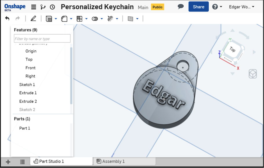
1.Intro to Solid Modeling & OnShape
There are many tools are our disposal for creating and working with 3D files, but for different purposes. Some 3D files are used for computer graphics, others as plans or blueprints for designing and constructing buildings.
For the purposes of 3D printing, the ideal tools are Solid Modelers; programs that work with solid 3D forms. The main distinctions between solid modelers and other 3D tools is the focus on the accurate physical properties of the designs. These tools understand that the objects you model are meant to be physical objects, which improves the quality and reliability of the files generated. Learning Solid Modeling opens a lot of opportunities for further exploration into Industrial Design, as it’s the industry standard used to create most consumer products today.
Traditionally solid modeling applications have been very expensive, and required powerful computer workstations making then available only to the larger companies who could afford them. Onshape, a free to use, cloud based solid modeler changes all of this, and makes it possible for almost everyone to develop and refine 3D designs with professional quality tools. The combination of free access and a cloud-based platform that can run on any computer, tablet or smartphone enables more people to work with the best tools.
2.Create an Onshape account
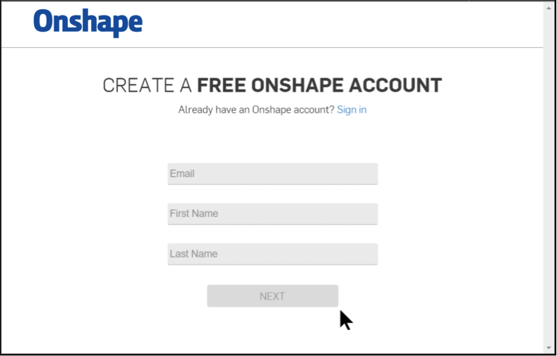
Start by opening up your web browser, and creating a new Onshape account at: https://www.onshape.com/new/onshape-signup.
3.Create a new Document
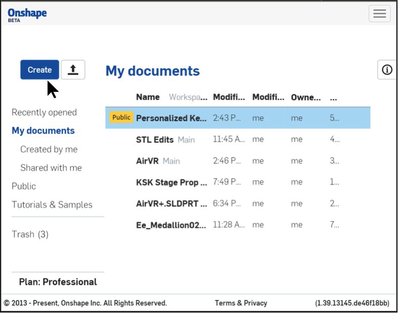
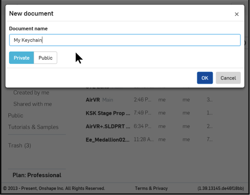
After creating an account and successfully logging in, click the blue “Create” button in the left hand menu to make a new Onshape Document. A window will pop up, prompting you to name the document you are creating. Enter a new name like “My Keychain”, then click “OK” to continue. In Onshape, Documents are the workspaces that contain all the files for a particular project.
4.Model Keychain
After creating your new Document, Onshape will load the Part Studio, which is where we’ll be modelling the keychain.
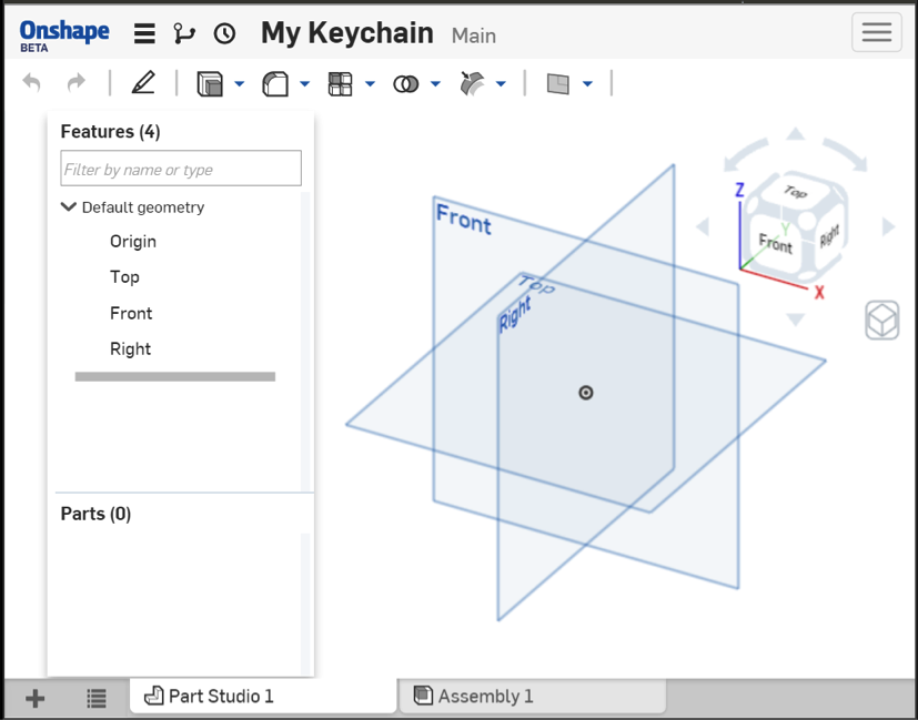
- This view has the grey File Menu at the top, with the Onshape logo, document name, and the settings icon (3 horizontal lines, sometimes called a Hamburger). The settings icon lets you change document settings like the name and dimensional units used.
- Directly below the File Menu is a context-sensitive Toolbar, containing the tools that are available to use. The tools will change based on what you have selected, and mode you’re working in. Sketch tools when you’re editing 2D sketches, solid modelling tools when you’re working with the solids.
- Exploring the toolbar is a great way to learn about the tools, if you hover over a button it will tell you it’s name and associated keyboard hotkey in parentheses. If you continue to hover, an explanation of the tools function will also appear.
- On the left hand side you’ll find the Features list. Features in Onshape are the objects in your file, operations you’ve performed on your solids with tools. Onshape remembers every operation you’ve ever done, so it’s easy to go back if you make a mistake at any point. By default it will contain the origin (absolute center of your file), and the top, front, and right planes. These planes are references that make it easier to align the sketches you’ll create to define your solids.
- At the bottom of the screen you’ll find the Document bar, which allows you to create and upload new files into your Document, and contains tabs for all of the files it already contains.
- The rest of the Onshape window is taken up view the main viewport. This view has the objects or sketches you’re currently looking at, and a navigation cube that lets you easily spin the view around.
Draw a Sketch
Most 3D solids or forms in Onshape start off as Sketches. Sketches are 2D vector drawings used to define the shapes and dimensions that Onshape will use to make your solid forms. Sketches are composed of shapes and lines, as well as relations you can define between different entities. This might sound complicated, but Onshape makes it easy to use. Let’s get started!
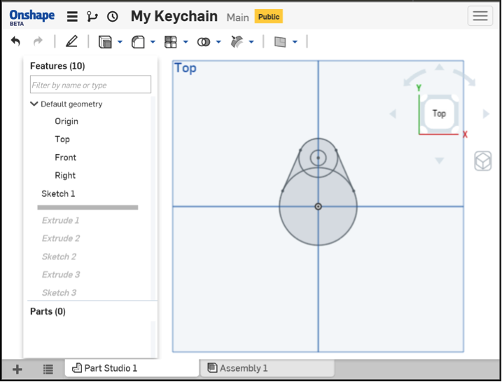
1. Create New Sketch: Start by right clicking on the Top Plane in the Feature List, then select “New Sketch…”, this will create a new sketch in the feature list.
2. View Normal to Sketch Plane: Now right click the main viewport, and select “View normal to sketch plane”. This will reposition the view perpendicular to the sketch, allowing you to sketch accurately. The other two planes (front, and right) also provide references for the vertical and horizontal midpoints, which we can use to keep things aligned.
3. Sketch First Circle: Now we’re all setup to sketch out the profile of our keychain. Select the Circle Tool from the Toolbar (or press the “C” key on your keyboard), and left click on the Origin (indicated as a black dot inside a small circle in the center of the sketch), when you place your mouse over it you’ll notice Onshape indicate it’s selected in yellow. When you move the mouse, you’ll create a blue outline preview of the circle you are about to sketch, left clicking again to create it.
4. Create Another 2 Circles: Using the Circle Tool again, click on the vertical line aligned with the Origin, just a bit above the first circle, make this circle smaller than the one from the previous step. Don’t worry about getting the dimensions perfect, Onshape lets you define shapes approximately at first, which we’ll add exact dimensions to separately in the next step. Now click in the center of the smaller circle you just created, Onshape will recognize the middle and highlight it in yellow. Drag out a circle a little smaller than the previous one, and left click to create it.
5. Add Dimensions: Select the Dimensions Tool from the top toolbar, or activate it by pressing the “D” key on your keyboard. We’ll use this tool to define the exact dimensions of the 3 circles, and the spacing between their centers. Click on the first circle you created, move the mouse to where you’d like to position the label and click to place it (don’t stress about the exact spot, these labels can easily be adjust later). Type in 1.6 and press Enter to define that circle’s Diameter as 1.6 Inches. You might notice the the scale of the view might change slightly, this is normal depending on how the shapes are being resized.
Use the Dimensions Tool to define the 2 circles you created in step 4 by clicking them, placing their label with another click and entering their diameters. The smallest one will be 0.3” and the larger one should be 0.75”. Once all the circles are defined, use the Dimension Tool to specify their spacing by moving your mouse to the bottom circle’s center, and clicking once Onshape selects it yellow. Repeat this on the center of the 2 smaller circles, and then finally place the label for the dimension. When prompted, define this dimension as 1”.
6. Create a Line using Auto-Constraints: Select the Line Tool from the top toolbar, or by pressing “L” on your keyboard. Click on the left side of the 0.75” circle and without clicking again, drag a line connecting it to the left side of the larger 1.75” circle. As you move the cursor along the circle’s circumference, you’ll notice small icons by the cursory, signifying potential auto-constraints. These constraints allow you to specify relationships between objects. In this case we’ll move the cursor along the larger circle until both the Coincident, and Tangent indicators are both visible. The Coincident icon is the first one from the left below and looks like a diagonal “T”. The Tangent indicator is fourth from the left, and looks like a diagonal line touching a small circle.

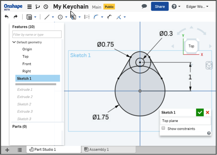
7. Manually Add Constraints: We were able to ensure the lines we drew were Tangential to the larger circle by using auto-constraints, but unfortunately the points at which the lines meet the 0.75” circle are Coincident, but missing the Tangent constraint.
Not to worry, adding constraints manually in Onshape is a breeze. Select the line on the left, and the 0.75” circle, then pick the Tangent constraint from the toolbar, or hit the “T” key on your keyboard. This will add a new constraint to the left line. Repeat these steps for the line on the right, and the profile of the keychain is complete!
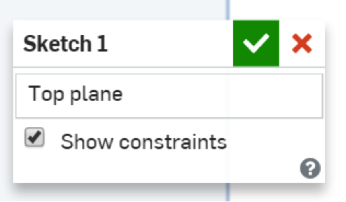
When you’re satisfied, exit the sketch by clicking the OK button at the top right of the sketch window.
Extrude Sketch into Solids
The sketch you created can now be used with the extrusion tool to create solid 3D models. When you exited out of the sketch, you may have noticed the tools in the Toolbar changed to the solid modelling set. These are tools we can use to create 3D forms from the 2D sketches.

1. Extrude base: Select the sketch you created, from the Features list on the left. Then pick the Extrude Tool from the toolbar (or press shift + “e” on your keyboard) to bring up the Extrude Window.
There are a few options in this window worth mentioning. First at the top there is the “Solid / Surface” option, this is for advanced operations and should just be set to Solid. Below that is the “New / Add / Remove / Intersect” toggle, these change what the extrude tool does with the shapes you define. New will turn each shape into a new 3D object, Add combines them all into a single 3D object, Remove subtracts, or cuts your 3D shape away from another object, and Intersect works only with the area where two objects intersect one another.
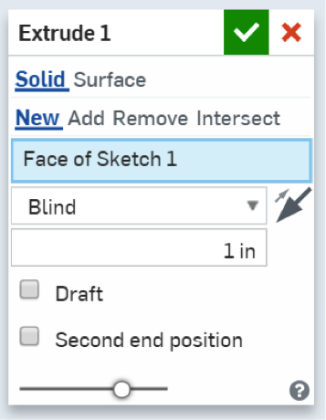
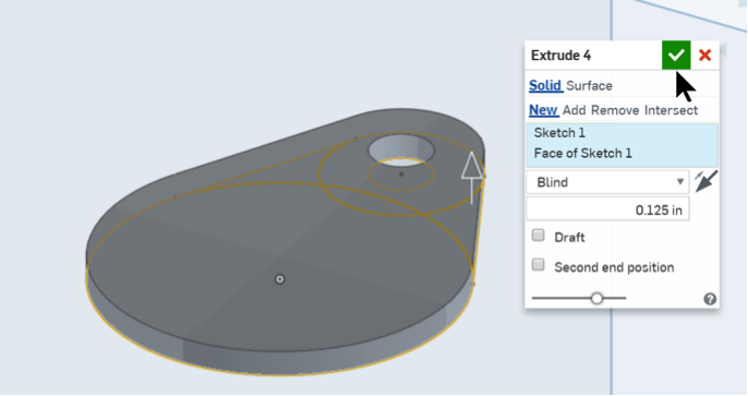
We’ll use this window to tell Onshape which of the shapes from our sketches we want to extrude. With the default options selected, change the dimension from 1” to 0.125”, and take a look at the 3D preview to make sure all the correct shapes are selected. If there are any weird gaps in the preview, zoom into the sketch and click on the pieces that are missing in the sketch at the bottom of the preview. Once you’re happy with the results, accept them by hitting the OK button at the top-right of the Extrude Window.
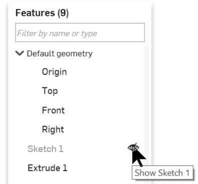
2. Unhide Initial Sketch: To keep the viewport tidy, Onshape will hides sketches when you use them for Extrudes. Unhiding will allow us to re-use the sketch for multiple extrudes. Hover the mouse cursor over your sketch in the Feature List on the left, and you’ll notice a visibility indicator on the right side of the list (small eye, with a line through it). Clicking the Visibility Indicator will show, or un-hide your sketch.
3. Extrude main circle: With your sketch visible, you can now select the Extrude Tool (shift + e) and select the large circle on it’s own. You might find it difficult to select the sketch shapes because they’re “under” the base extrusion, but you can right click and pick “Select other…” from the menu to bring up a popup with a list of possible selections.
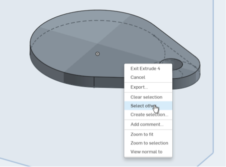
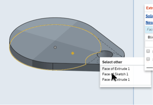
Hover your mouse over the list and Onshape will indicate the faces in yellow. You’ll notice that there might be a small piece missing out of the extrusion preview when you first select the big circle. You can just right click on the small shape in the sketch, and pick “Select other…” again to pick the remaining piece of the circle. Change the length of the extrusion from 1” to 0.5” and accept it by clicking the green checkbox in the upper right corner.
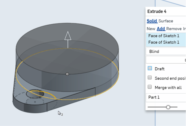
4. Personalize with Text: The last step in this sketch will be to personalize the keychain with a name or word.
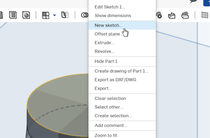
Right click on the top face of the circular extrusion from the previous step and select “New sketch…”, this will create a second sketch, which will rest on the top circular face, rather than resting on the Top Plane (the one in the Features list) where the existing solids have been extruded from (bottom of the keychain). Right click on the sketch, and select “View normal to sketch plane” from the popup menu.
Select the Text tool (an “A” with a dashed box around it), and drag out a rectangle approximately the size you want the text, below the keychain. Drawing this bounding rectangle below the keychain makes it easier to do so without accidentally creating auto-constraints that may get in the way.
After you create the rectangle, Onshape will bring up the Text Window, allowing you to enter your text, and select the font and styling used. Enter your name or something that’s special to you, and pick a font you like from the dropdown list on the left. When you’re happy with the results, accept by clicking the green check-box at the top-right of the window.
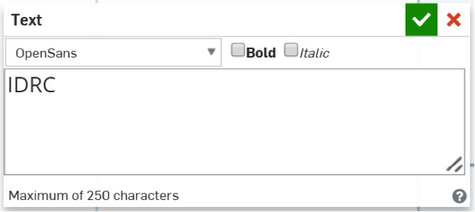
Onshape will place the outlines of your Text inside a box with a dashed outline. In Onshape sketches, these dashed lines are Construction Lines that can be used for alignment and referencing shapes, but won’t show up when we start extruding these shapes into 3D solids. Notice the box also has a vertical dashed line at it’s center, we’ll be using this shortly. Select the Dimensioning tool (hotkey: d), click on the top, horizontal dashed-line and place a dimension label, setting the length to 1.5”. Once the text has been resized to fit inside the keychain, we’ll create a point to help us center it.

Select the Point tool from the toolbar (a small circle, left of the Text tool) and move your mouse to the middle of the vertical construction line in the center of the text. Onshape will select the line and midpoint, and show a “Midpoint” auto-constraint indicator next to your cursor. Left click to place the point with the auto-constraint.
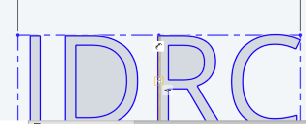
All that is left is to center the text onto the keychain itself, before we can start extruding 3D solids. Select the point you created, and the point at the Origin (at the center of the 1.75” circle), and then pick the Coincident constraint from the Toolbar (hotkey: i). This will align the text to the keychain. Feel free to explore different dimensions and spacings if you’d like to customize the keychain even further.
5. Subtract name
If you experience any snags along the way, check out Onshape’s “Let’s Make a Part” video tutorial
5.Download model as STL
Congratulations! Now that you have created your first solid model from scratch, all that’s left is to download the file in a suitable format, and to steps 2-4 from the previous lesson. Right click the “Part Studio 1” tab, in the status bar at the bottom left of the screen, and select “Export…” from the popup menu.
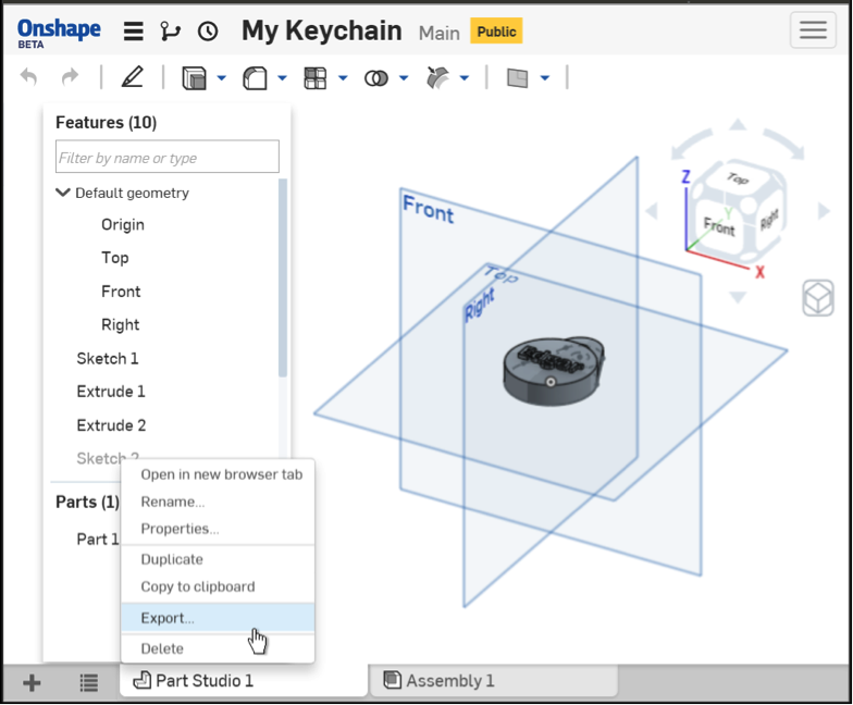
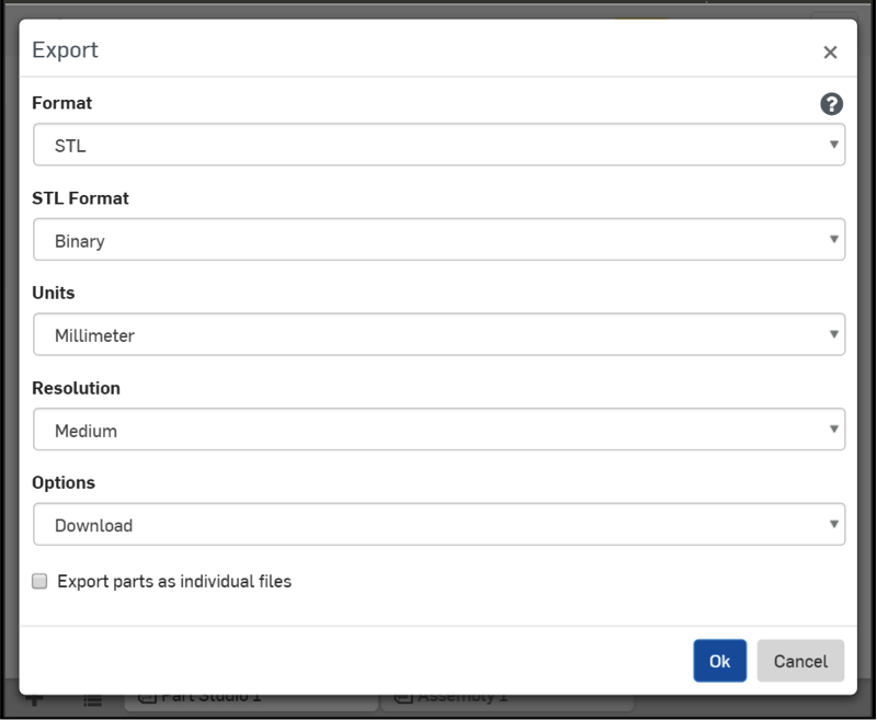
This will bring up the Export window. Change the “Format” to “STL”, and ensure that “Units” is set to “Inches”, then click “OK”. This will convert your keychain model into a STL file, and then download it.
6.Prepare files
If you’re planning on having your part printed for you, your files are already in the correct format. Skip ahead to the Print section.
If you have access to a 3D printer directly, then you’ll need to convert your .STL file to a format that the 3D printer can read. 3D printer manufacturers usually provide these applications, or Slicers on their websites.
The specific steps will vary slightly from application to application, but the general process is the same with most slicers:
1. Import model: The first step is getting your model (.STL file) into to slicer. Most will have a button containing “import”, “add file”, or “+”. Use this button to select the file you exported to the folder on your Desktop
2. Set print options: For basic prints, the default print settings in most slicers are a good balance of print quality and speed, so you shouldn’t have to do any adjustments.
- infil
- layer height
- supports
- rafts
3. Slice model: Now you’re ready to do the slicing! In cases where you’re going to be printing to the 3D printer directly over a USB cable, the slicing or “printing” process will automatically take care of the next 3 steps. The downside to using a USB cable is that it requires a dedicated computer for the duration of the print. If you choose this option, you can proceed to the Print step below.
Many 3D printers also support external media like memory cards or usb flash drives. These are a great option for doing prints without tying up a computer. First, insert your memory card or usb key into your computer. Next, depending on the slicer, the option may be called something similar to “Export Print File” or “Print to SD Card”. Clicking this button will initiate the printing
4. Transfer file to printer: Insert the memory card or usb key into the 3D printer, and use its interface to navigate to your file. Once you’ve located your file, you’re ready for the next step. If you’re not quite ready to start the print just yet, and your printer supports it; preheating the 3D printer is a great way to reduce the wait time.
7.Print
This step may start automatically if you chose to transfer your print over USB cable. If you opted for external media, then do a final check to ensure that you have enough filament in the machine, and start the print! If possible, keep an eye on the print and look at how the printer creates your piece, slice by slice. This also ensures that if anything goes wrong, you’re there to hit the cancel button and stop the machine from doing further damage. Bed alignment issues, and a lack of adhesion to the print bed can cause prints to lift and move as they’re printing, which can sometimes have disastrous results. If you experience any issue, stop the print immediately, clean off the print bed and recalibrate the printer, then restart the print.
8.Post Processing
Finish your keychain off with some light sanding, and put a split-ring / key ring through the hole and you are done. Look below for more tips on learning more of the tools available in Onshape!
Congratulations again! You have now learned how to solid model, which can use to create custom 3D objects. Feel free to create a new document in Onshape and explore some of the other tools in the modeling and sketch view. Check out the Onshape Tutorials section in Additional Resources for in depth video tutorials that teach more of the advanced functionality found in Onshape.
Task
3D design and print your personalized keychain. Afterwards, share your response to "What would you like to do next with a 3D Printer?"
Bonus Task 1 - 3D scanning with a smartphone
- There are a number of apps available that turn your smartphone into a 3D scanner capable of generating
Bonus Task 2 - Spiral Printing
In most cases, 3D printers fabricate objects one layer or slice at a time, but there are certain cases in which a FDM printer can create shapes by tracing a single continuous spiral without having to lift the hotend. This reduces the print time and results in very nice looking prints that are relatively light because of their lack of infill. For best results, files need to be created with this printing method in mind.
This is an option that would be set during the slicing phase, so please refer to the 3D printer’s documentation for instructions on how to enable the spiral printing mode.
Some examples suitable for spiral printing:
- Vase Trifecta by AK_Eric
- Customizable Star / Ellipse / Polygon Vase, Pen / Flower Pot Creator by iamburny
- Perfect Low Poly Ready 2 Print Vase by Norwegian1
- SPIRAL vase by be3D_printers
- WAVE 01|02|03|04 by Zampik
Submissions (1)
-
Tania Rashid Discussion post: 3616 days ago
